
In this guide, we will go through step-by-step how to use Asiga Composer software to nest 3D mesh files (.STL, .PLY, .SLC, .STM) and prepare jobs ready to send to any Asiga 3D printer. Before starting, ensure that you have installed Asiga Composer.

First, open Asiga Composer and start a new build by clicking the button on the left. This will open the New Build menu which gives options for the build properties.
Build Properties
Second, use the menu to select your printer from the list connected to the internet. If it is not showing, check that the printer is on and connected to same network.
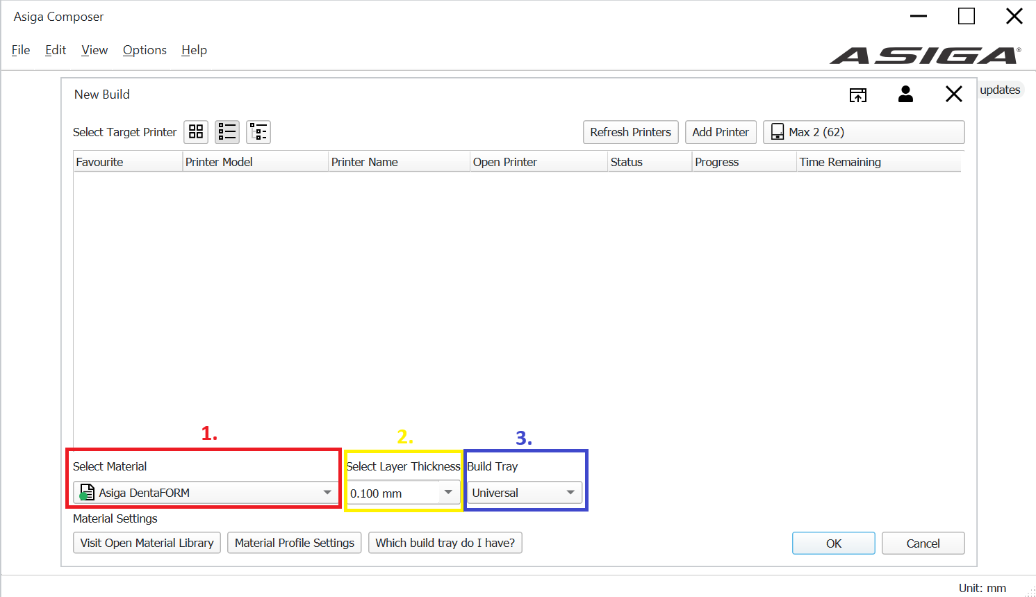
In addition to the printer, the menu displays build properties; attributes giving the printer preset configuration values for material, layer height, and build tray.
- Select the material. Asiga materials are preinstalled. Third-party materials validated by Asiga can be downloaded and imported into Asiga composer.
- Select the layer height: Smaller layer heights result in higher quality but longer print time. Larger layer heights are significantly faster to print. The following layer heights are recommended for indications:
- 0.150mm: Dental models
- 0.100mm: Orthodontic
- 0.50mm and below: Restorations
- Select the build tray you are intending to use.
Note that only one material, layer height and tray can be selected for one build. For indications with multiple materials such as dentures, each unique set of build properties must be placed in separate builds.
When all the settings are confirmed, press OK to continue. Build properties are available to change later on the side panel.
Navigating the Build Area
Once build properties are set, the build area will become visible. Asiga Composer has the following default controls for navigating the build area:
- Left click: Pan view. If held over a part, it will drag the part instead of panning.
- Right click: Rotate view. If held over a part, it will rotate the part instead of the view.
On the top panel, there are also icons for more navigation functions.
- Top/Bottom, Front/Back, Left/Right views
- Perspective/Isometric view toggles
- Zoom in/out buttons

Left click to pan, right click to rotate view, top panel buttons for preset viewing angles: Top/bottom, front/back and left/right.
Add parts
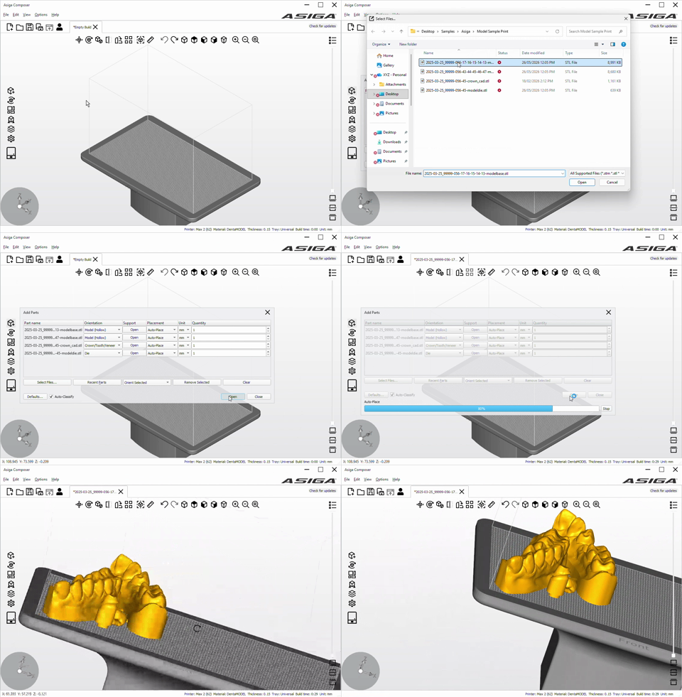
Next, we will be adding parts to the build area. On the left side panel, click the “Add parts” button. Press “Select Files…” to browse and select STL or PLY, SLC or STM files to place on the build platform.
Arrange Parts
With parts in the build area, Asiga Composer has several tools to arrange them:
- Auto-orient: Orients the part’s rotation based on the restoration type and automatically detected features.
- Auto-place: Nests parts inside the build area. Advanced options enable toggling XY and Z placement individually, as well as distances between parts and edge of platform.
- Rotate facet downwards: Select a face on the part to automatically point it towards the build platform surface.
- Move: Manually move a part a set amount in x, y and z coordinates.
- Rotate: Manually rotate a part at an angle interval or automatically rotate from part features

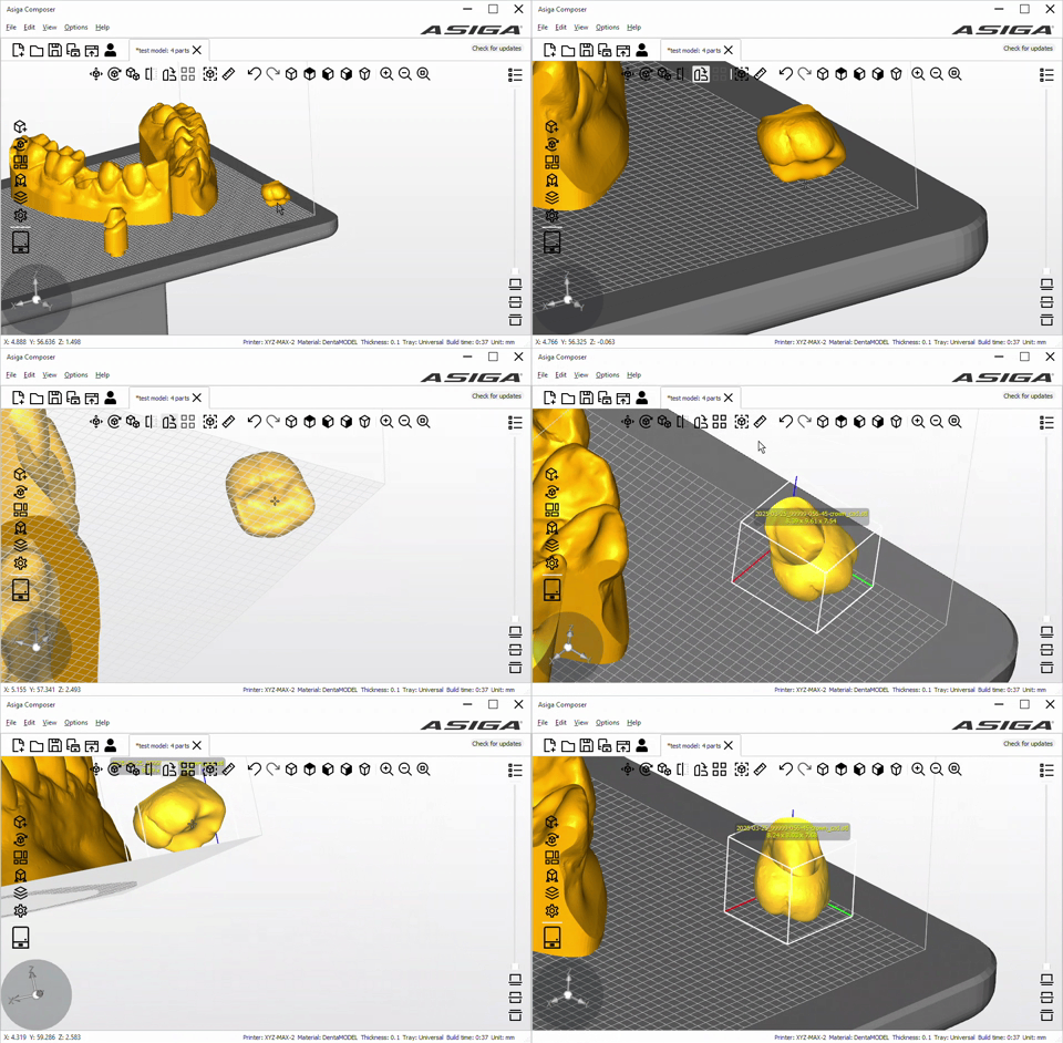

It is recommended to use auto-orient then auto-place or rotate facet downwards for specific orientation. Then, you can adjust parts manually with the move and rotate tools if required. This is sometimes necessary when arranging many parts close together, as auto-place may not detect where there is sufficient space. Use the top panel navigation buttons for top, front/back, left/right views when moving or rotating in specific planes.
Parts are yellow when in the build area. If the part is magenta, it is outside the build area and will have to be moved back in. Ensure that no parts are colliding with each other before continuing.
Add Supports
Most dental restorations will need support structures, with the exception of dental models with the flat base on the build platform and no trapped volume. Asiga Composer has a built-in feature to auto-generate supports.
To add supports, click on the “Generate Support” icon on the left-hand side. With the parts selected and the “Generate Support” window open, click “apply”. This will automatically generate supports. In the case where supports have to be added, removed or customised, click “Advanced” for more options.

Check the Print
Before sending the print to the Asiga printer, ensure that parts are inside the build area and there are no collisions. Place supports such that all overhanging areas are supported in a balanced way. If supports are insufficient, floating parts can tip over during the print, causing a print failure.
Use the clipping slider on the right-hand side and the 3 buttons for views on different layers to ensure the parts are contacting the build platform, and that there is no trapped volume. This is also used to check that overhanging or floating areas are supported properly.

Save the Build
Under the file tab, save the build as a .combld file. This saves the build properties, part positions and orientations which can be opened again in Asiga Composer.
Send to Printer
Click the printer icon on the left-hand side. This will show some options:
- Fast Print: Recommended for all prints for faster print times.
- Separation Detect: Faster print times when turned on. Recommended to turn off for high surface area prints such as dentures or full arch models.
Send the job to the printer to be started from the printer’s touchscreen interface.

After Job is Sent to Printer
Once Asiga Composer has sent the job to the printer, it will appear on the printer’s interface. From there, prepare the printer with the matching material and build tray, and start the print. If the materials are already prepared, you can use the front panel on the web interface start the print.